Types of Position Sensors
Position sensors are generally divided into two types based on the way of sensing.
They are
- Contact Devices
- Non-contact Devices
As the name indicates, the contact types of position sensors have the physical contact with the measurand. The contact based sensors are Limit Switches and Resistance based position sensors. Contact based sensors provide simple and low cost solutions in applications where physical contact with the object is acceptable.
Non-contact devices don’t involve in physical contact with the object. They are magnetic sensors, proximity sensors, Hall Effect based sensors and ultra-sonic sensors.
Every position sensor has its benefits and limitations. The goal is to select a sensor that is a cost effective solution for parameters of a specific application.
Resistance based or Potentiometric Position Sensor
Resistive position sensors are also called as Potentiometers or Position Transducers. They are originally developed for applications in military use. They were used in radios and televisions as panel mounted adjustment knobs. Potentiometers can work as linear or rotary position sensors.
Potentiometer doesn’t require a power supply or extra circuitry to perform their basic position sensing function. Hence, they are passive devices. They are operated in two modes: voltage divider and rheostat. In rheostat, the resistance varies with motion. Hence the applications make use of this varying resistance between fixed terminal and a sliding contact. Voltage divider has the true potentiometric operation. In this, a reference voltage is applied across a resistive element. The position of the movable wiper is determined by calculating the voltage picked up by the wiper.
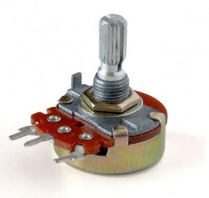
Potentiometers are the most commonly used position sensors. It has a fixed terminal and a wiper terminal connected to a mechanical shaft. The movement can be either linear (slide) or angular (rotational). This movement causes the resistance between fixed and wiper terminals to change. The output electrical signal which is generally voltage varies in proportion to the position of the wiper resistive track and hence the value of the resistance.
Potentiometers are available in different sizes and designs. The commonly available types are linear slider and rotational type. When it is used as position sensor, the object is connected to its slider.
Image Resource Link: en.wikipedia.org/wiki/Potentiometer
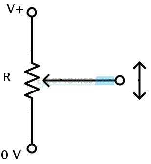
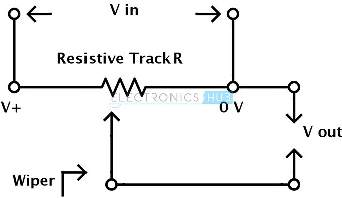
A reference voltage is applied between the fixed terminals which are on the either side of the wiper and the output voltage is taken from this wiper. This configuration forms a voltage divider network and the output voltage is dependent on the position of the slider.
If a potential of 12 V is applied to the potentiometer, a maximum of 12 V and a minimum of 0 V is available as the output voltage. Depending on the position of the wiper, the output voltage can be any value between 0 V to 12 V. If the wiper is at the center of the resistive track, the output voltage is 6 V.
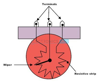
The construction of a potentiometer is shown in the below figure.
For general purpose position sensing, a low cost potentiometer is sufficient. The advantages of the potentiometers are low cost, simple operation, simple application theory, easy to use and robust EMI susceptibility. The disadvantages are eventual wear-out due to sliding wiper, lesser sensing angle and low accuracy. The main disadvantage of potentiometer based position sensor is its physical size as it limits the movement of the slide and hence the output signal. The sensing angle of a typical potentiometer is in the range of 00 to a maximum between 2400 and 3300. Vernier turns can be applied to achieve multi-turn capability.
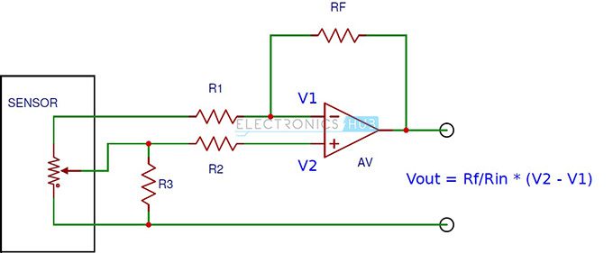
A simple position sensing circuit is shown below.
It consists of an OP amp and a potentiometer based position sensor. The output voltage depends on the position of the wiper.
Carbon film is the most common type of resistive track used in potentiometers. But there is a contact noise that is superimposed in the expected resistance. Contact noise is the result of mechanical contact between wiper and resistive surface. This can cause up to 5 % of the total resistance.
Wire wound type potentiometers use a straight wire resistive element or coil wound resistive wire. The problem with wire wound potentiometers is the jumping of wiper between positions producing a logarithmic output signal.
Polymer film or cermet type potentiometers are available for high precision and low noise applications. These are made up of conductive plastic resistive material. They have very less friction between the wiper and the surface and therefore less electrical noise, good resolution and longer life. These are available as both single turn and multi turn devices. These devices are used in high accuracy applications like joysticks, industrial robots etc.
Capacitive Position Sensors
Capacitive Sensors are non-contact type of devices used for precision measurement of a target position if the target is conductive in nature, or used for measurement of thickness and density of a material if the target is non-conductive in nature. When used with conductive targets, they work irrespective of the material of the target as all conductors look same to a capacitive sensor. The thickness of the target is also not important as the sensors sense the surface of the target. They are mainly used in disk drives, semiconductor technology and high precision manufacturing industries where high accuracy and frequency response are important. When used with non-conductive targets, they are generally used in label detectors, coating thickness monitors, and paper and film thickness measuring units.
They are primarily used in measurement of linear displacement from a few millimeters to nanometers. Capacitive sensors make use of the electrical property conductance for measuring position. The ability to store electric charge by a body is capacitance. The most common device used to store charge is a parallel plate capacitor. The capacitance of a parallel plate capacitor is directly proportional to the surface area of the plates and dielectric constant, and inversely proportional to the distance between the plates. Hence, when the spacing between the plates is changed, there is a change in its capacitance and capacitive sensors make use of this property.
The capacitance,
C = (εr εo A) / d
Where
εr is relative permittivity of dielectric
εo is permittivity of free space
A is the overlap area of plates
And d is distance between the plates
A typical capacitive sensing model consists of two metal plates with air in between them acting as dielectric. The sensor or probe is one of the metal plates and the target object which is conductive, is the other plate.
When a potential is applied to the plates of the conductor, an electric field is created between them by causing positive charges to collect on one plate and negative charges on other.
Capacitive sensors use alternating voltage. Alternating voltage causes the charges to continually reverse their positions. The alternating electric field between the capacitive probe and the target is monitored for changes and is used in measuring the capacitance between the probe and target. Capacitance is determined by the area of the surfaces, dielectric constant and spacing of the surfaces. In the majority of capacitive sensing applications, the size and area of the capacitive sensor and the target do not change. The dielectric material between the conductive surfaces doesn’t change. The only factor responsible for any changes in the capacitance is the distance or spacing between the capacitive sensor and the target.
Hence the capacitance is an indicator of the target’s position. Capacitive sensors are calibrated to produce an output voltage corresponding to the change in distance between the probe and target which causes the capacitance to change. This is called the sensitivity of the capacitive sensor. Sensitivity of a capacitive sensor is the amount of voltage change to a defined amount of distance change. Generally used sensitivity setting is 1 V / 100 µ m i.e. the output voltage changes 1 V for every 100 µ m change in distance.
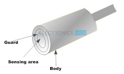
A capacitive sensor probe consists of three components: sensing area, guard and body.
The potential is applied to the sensing area. There is a problem of spreading of an electric field to areas on the target other than the defined sensing area and the target. To prevent this from happening, a technique called guarding is used. In this technique, a guard area is created by surrounding the sides and back of the sensing area and is maintained at a potential same as the sensing area. As the guard and the sensing area are at the same potential, there will be no electric field between them. Any other conductors in the proximity other than the sensing area will form an electric field with the guard. The sensing area and the corresponding target are undisturbed.
Because of this guard, the electric field projection of the sensing area will be conical in nature. The electric field from the probe covers an area on the target of approximately 30 % larger that the sensor area. Therefore, it is essential to have a minimum target diameter as 30 % of the sensing areas’ diameter for standard calibration.
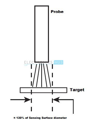 The range of a sensing probe is directly proportional to the size of the sensing area. Smaller probes must be placed closer to the target in order to achieve the desired amount of capacitance. The maximum allowable gap between the probe and the target is approximately 40% of the diameter of the sensing area. Beyond this, the probe becomes useless. There are applications where multiple probes are simultaneously used. In these applications, it is essential to synchronize the excitation voltage of all the probes. If the voltages are not synchronized, the probes interfere with each other as one probe may try to increase the electric field while the other decreases it. This gives a false reading.
Capacitive Sensors can also be used with non-conducting targets. The dielectric constant of the non-conductive target is the basis for the operation. The dielectric constant of the non-conductive materials like plastic is different than air. When the non-conducting material is used as a dielectric medium between two conducting plates, its dielectric constant will determine the capacitance between the conductors.
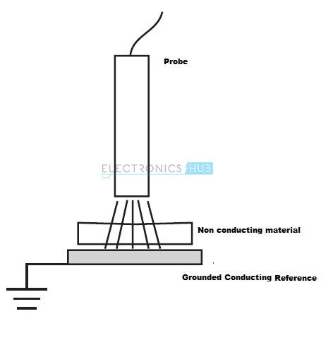 The two conducting plates are sensor probe and a grounded conductive reference. The changes in capacitance and hence the output of the sensor will be corresponding to the changes in material thickness, density or composition.
There are high precision and high performance capacitive sensors that can measure a displacement of the order of nanometers. These high performance sensors are stable to changes in temperature, produce a linear output and have high resolution.
The advantages of capacitive sensors over other non-contact devices are high resolution, inexpensive and not sensitive to the material of the target. The capacitive sensors are not suitable in conditions where the environment is dry or wet and the distance between the probe and the target is large.
Inductive Position Sensors
Inductive Sensors are non-contact type of devices used for precision measurement of a target position if the target is conductive in nature. Inductive sensors are used to recognize any conducting metal target.
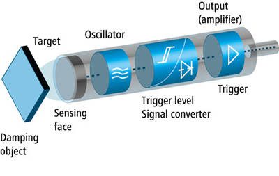
Capacitive sensors make use of electric field for sensing the surface of a conducting target. Inductive sensors make use of electromagnetic field that penetrates through the target. An inductive sensor probe consists of an oscillator that generates a high frequency electromagnetic field. This field is radiates from the sensing face of the probe.
Image Resource Link: baumer.com/typo3temp/pics/User_Knowledge_Presence_Inductive_Functionality_sensor_EN_216cc0d8dd.jpg
When this field contacts a conducting metal target, a small current is induced within the metal target. These currents will generate their own electromagnetic field that interferes with the field originating from the probe. This causes a change in the amplitude of the oscillations of the signals from the probe. The output voltage can be calibrated to this change. When the probe is closer to the target, the more current reacts with the field originating from the probe and the output is greater.
Unlike capacitive sensors, inductive sensors are independent of the material in the gap between the probe and the target. Hence, they can be used in hostile environment where oil or other liquids may appear in the gap.
The material of the target is an important factor in inductive sensors. Materials like aluminum, steel and copper, each react differently to the sensor. Hence the sensor must be calibrated for each target to achieve optimum to highest possible performance.
Generally there are two types of target materials for inductive sensors. They are ferrous and nonferrous. Ferrous materials are magnetic in nature while nonferrous materials are nonmagnetic. Ferrous materials include iron and most steel materials while nonferrous materials include zinc, aluminum, copper and brass. Some inductive sensors will work with both ferrous and nonferrous target materials while others will work only with one type of material.
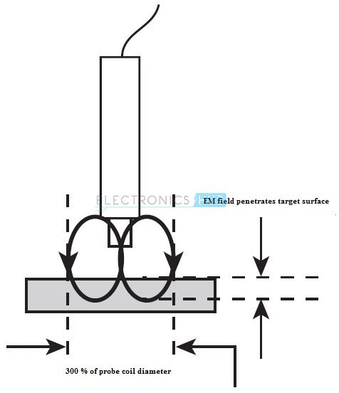
The size of the target is also important as the effective area of electromagnetic field of the probe will vary from sensor to sensor. It is a minimum requirement to have the cross sectional area of the target of at least 300 % of the probe’s coil diameter, i.e. ideally the surface area of the target must be at least three times the diameter of the probe.
The thickness of the target is also an important factor as the electromagnetic field will penetrate the target and creates electrical currents. The thickness of the target depends on the frequency of the signal which drives the probe and is inversely proportional to the frequency, i.e. when the drive frequency increases, the minimum thickness of the target decreases.
For a drive frequency of 1 MHz, the minimum thickness of some commonly used target materials is as follows:
- Iron—0.6 mm
- Stainless Steel—0.4 mm
- Copper—0.2 mm
- Aluminum—0.25 mm
- Brass—1.6 mm
Inductive sensors with analog output signals are known for their nanometer resolution, short response time, frequency responses of 80 KHz or more, repeat accuracy and immunity to environmental contaminants.
The output voltage and current of an inductive sensor is directly proportional to the distance between the surfaces of the sensor and the target, i.e. the voltage and current represent the absolute measured values corresponding to the distance. This property is used in numerous applications.
Linear Variable Differential Transformer (LVDT)
The Linear Variable Differential Transformer (LVDT) is a common type of electromechanical, high resolution, contact based linear position transducer. LVDT is one of the best available, reliable and accurate methods for measuring linear distance. LVDTs are used in computerized manufacturing, machine tools, avionics and robotics.
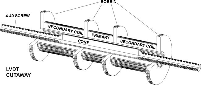
Linear Variable Differential Transformer is a position to electrical sensor. An LVDT consists of three coils, one primary and two secondary. A movable magnetic core is placed as shown in the figure. This magnetic core which is also called an armature controls the transfer of current between primary and secondary coils in the LVDT. The output of the LVDT is proportional to the position of the core.
A cross sectional view of the LVDT is shown below.
Image Resource Link: keckec.com/seismo/images/lvdtbig.gif
The magnetic core moves linearly inside the transformer consisting of a primary coil and the two identical outer secondary coils that are wound in a cylindrical manner.
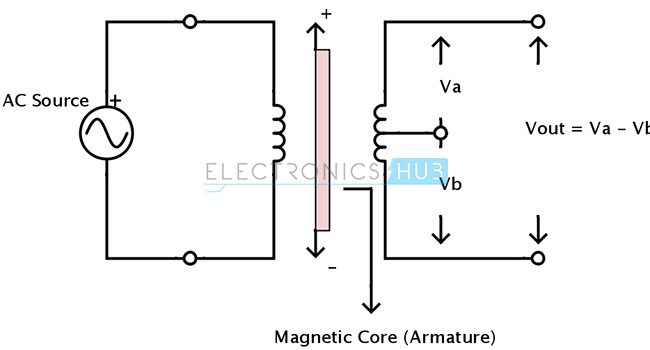
When the primary coil is excited with an alternating current, a voltage is induced across secondary coils. The secondary coil voltage varies according to the position of the magnetic core between the coils which moves axially. The output electrical signal is equal to the difference between the voltages across the secondary windings. Therefore the output voltage is proportional to the linear mechanical movement of the magnetic core.
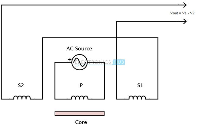
A normal transformer style representation of the LVDT is shown below.
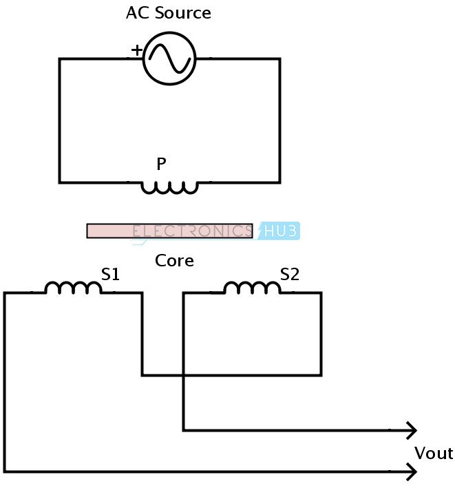
The schematic representation of an LVDT is as shown below.
Working of LVDT:
The primary coil of the transformer is energized by applying an alternating source of constant amplitude. This generates a magnetic field and the developed magnetic flux is coupled to the secondary coils S1 and S2 by the magnetic core in the center. The secondary coils are wound out of phase with each other. Therefore, when the position of the core is exactly midway between the two secondary coils, equal amount of magnetic flux is coupled to S1 and S2. The voltages induced in each of the secondary coils V1 and V2 are equal. Hence the output differential voltage Vout is equal to zero.
V1 = V2
And
Vout = V1 – V2 = 0
When the coil moves away from the center, the voltage induced in each secondary coil is different. When the core is moved towards S1, the magnetic flux coupled with S1 is greater than that is coupled with S2. Therefore the induced voltage V1 increases and V2 decrease.
The differential output voltage is Vout = V1 – V2.
If the magnetic core or armature moves towards the secondary coil S2, the magnetic flux coupled with S2 is greater than S1. And the induced voltage V2increases while V1 decreases.
Therefore,
the output voltage is Vout = V2 – V1.
The phase of the output signal can determine the position of the core.
Simply the output voltage of LVDT will not determine the position of the core if there are any mismatches between the secondary coils or any leakage inductances. A signal conditioning circuit is useful in removing these difficulties.
A normal LVDT is shown below.
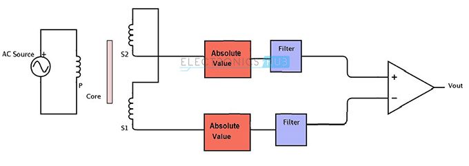
LVDT with the signal conditioning circuit is shown below.
It consists of additional filtering and amplification circuit where the absolute values of the two output signals are subtracted. The absolute value circuit can be formed from a diode capacitor rectifier. Filters are used to detect the amplitude of both the secondary voltages. This technique is useful in measuring both the positive and negative variations about the center position.
LVDT has a huge advantage over the potentiometer as a position sensor in many ways. Since the magnetic core doesn’t touch the coils, there is no mechanical contact between the coils and the core. Hence a frictionless operation is achieved and is useful in testing and high resolution devices. This is also an important factor in their longer operation life.
Because of its electromagnetic coupling principles and frictionless operation, LVDT can measure infinitesimally small changes

No comments:
Post a Comment